Activity 4.2.1 — Microcontrollers & Microprocessors
Learning Objectives
By the end of this lesson, students will be able to:
- Distinguish between microprocessors and microcontrollers
- Describe the internal architecture of a microcontroller
- Identify key features of the Arduino platform
- Compare discrete logic with microcontroller-based solutions
- Determine when to use each approach
Vocabulary
Vocabulary (click to expand)
| Term | Definition |
|---|---|
| Microprocessor | A CPU-only chip that requires external memory and I/O |
| Microcontroller | A complete computer on a single chip (CPU + memory + I/O) |
| CPU | Central Processing Unit - performs arithmetic and logic operations |
| RAM | Random Access Memory - volatile storage for data |
| ROM/Flash | Non-volatile memory for program storage |
| I/O Ports | Input/Output pins for connecting external devices |
| ADC | Analog-to-Digital Converter - converts analog signals to digital |
| IDE | Integrated Development Environment - software for writing/uploading code |
Part 1: What is a Microprocessor?
Definition
A microprocessor (MPU) is the “brain” of a computer - it performs all arithmetic and logic operations. However, it cannot function alone.
Required External Components
A microprocessor needs external circuits to work:
| Component | Function |
|---|---|
| ROM | Stores the program (permanent) |
| RAM | Stores temporary data |
| I/O Controller | Manages input/output devices |
| Clock Circuit | Provides timing signals |
| Bus Controller | Manages data flow between components |
Example: Intel 8086
The 8086 was an early microprocessor used in IBM PCs:
- 16-bit data bus
- 20-bit address bus
- Required ~20+ external components to function
Advantages of Microprocessors
- Very flexible
- Can handle complex computations
- Used in personal computers, servers
Disadvantages of Microprocessors
- Requires many external components
- More complex circuit design
- Higher power consumption
Part 2: What is a Microcontroller?
Definition
A microcontroller (MCU) is a “computer on a chip” - it contains everything needed in a single package.
Microcontroller Architecture
┌─────────────────────────────────────────────────────────────┐
│                    MICROCONTROLLER                          │
│  ┌─────────┐    ┌─────────┐    ┌─────────┐    ┌─────────┐ │
│  │   CPU   │◀──▶│   RAM   │◀──▶│  Flash  │◀──▶│  I/O    │ │
│  │         │    │ (data)  │    │ (program)│   │  Ports  │ │
│  └─────────┘    └─────────┘    └─────────┘    └─────────┘ │
│       │                                           │        │
│  ┌────▼───────────────────────────────────────────▼────┐  │
│  │                    BUS SYSTEM                     │  │
│  └───────────────────────────────────────────────────┘  │
│                                                             │
│  Optional Peripherals:                                     │
│  - Timers/Counter      - ADC (Analog to Digital)          │
│  - Serial UART         - PWM generators                   │
│  - SPI/I2C bus         - interrupts                       │
└─────────────────────────────────────────────────────────────┘
Key Components
| Component | Description |
|---|---|
| CPU | Executes program instructions |
| ROM/Flash | Stores the program (non-volatile) |
| RAM | Stores variables and temporary data |
| I/O Ports | Pins to connect LEDs, buttons, sensors |
| Timers | Generate precise time delays and intervals |
| ADC | Convert analog voltages to digital values |
Popular Microcontrollers
| Microcontroller | Manufacturer | Typical Use |
|---|---|---|
| ATmega328P | Atmel (Microchip) | Arduino Uno |
| ATmega2560 | Atmel | Arduino Mega |
| STM32 | STMicroelectronics | STM32 boards |
| ESP32 | Espressif | WiFi/Bluetooth |
| PIC16 | Microchip | Industrial |
Part 2: Arduino as a Microcontroller Platform
Why Arduino?
Arduino is a popular microcontroller platform because:
- Easy to use (beginner-friendly)
- Open source hardware
- Large community support
- Inexpensive
- USB programming
Arduino Uno Specifications
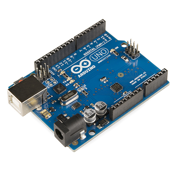
| Feature | Specification |
|---|---|
| Microcontroller | ATmega328P |
| Operating Voltage | 5V |
| Input Voltage | 7-12V (recommended) |
| Digital I/O Pins | 14 (6 provide PWM) |
| Analog Input Pins | 6 |
| Flash Memory | 32 KB |
| SRAM | 2 KB |
| Clock Speed | 16 MHz |
| USB | Type-B connector |
Arduino Board Layout
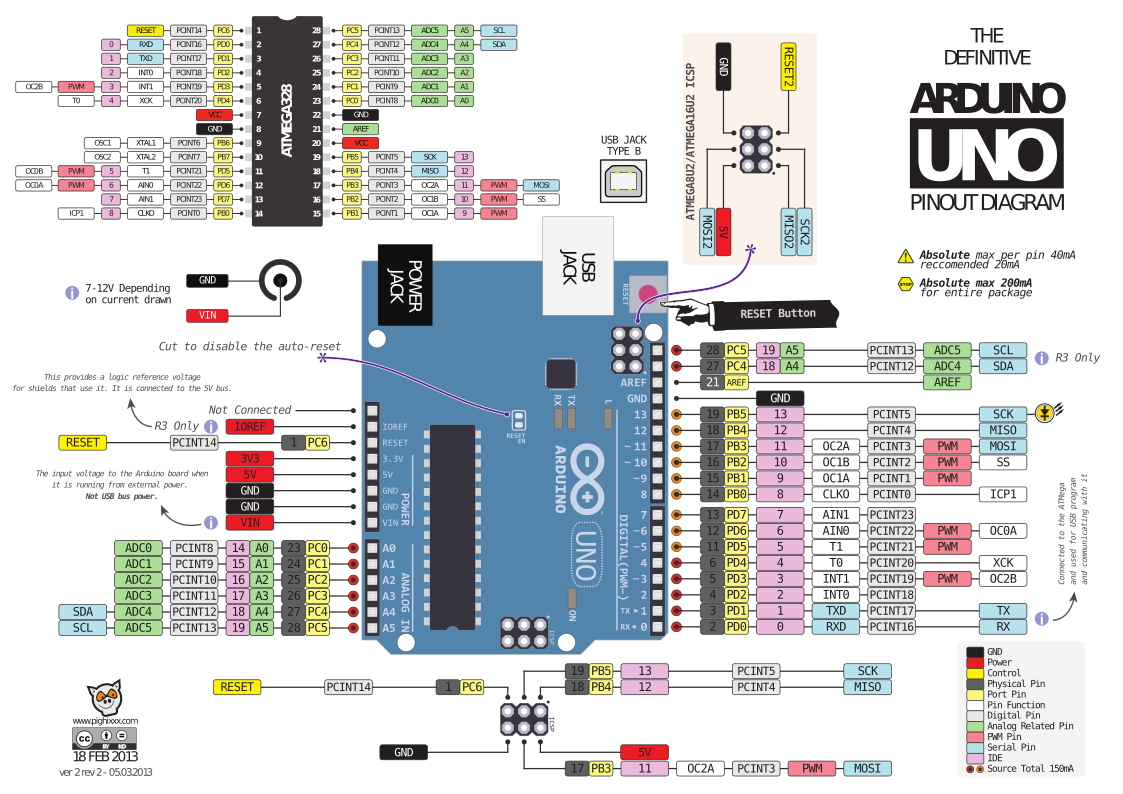
                    Arduino UNO
    ┌────────────────────────────────────────────┐
    │                                            │
    │  USB        ┌──┐                          │
    │  Connector  │RST│  ← Reset button         │
    │             └──┘                          │
    │                                            │
    │  ┌─────▼───────────────────────────────┐   │
    │  │         Power & Analog Pins        │   │
    │  │ GND  AREF  SDA  SCL  [Analog]      │   │
    │  └────────────────────────────────────┘   │
    │                                            │
    │  ┌────────────────────────────────────┐   │
    │  │         Digital I/O Pins          │   │
    │  │  SCL  SDA  A0  A1  A2  A3  A4  A5  │   │
    │  │  └─────────▼─────────┘             │   │
    │  │         ~ pins = PWM               │   │
    │  └────────────────────────────────────┘   │
    │                                            │
    │  ┌────────────────────────────────────┐   │
    │  │      13──●──12  11●──10──●──9──●   │   │
    │  │       LED    Digital I/O          │   │
    │  └────────────────────────────────────┘   │
    │                                            │
    │      ┌──────┐    Power Jack               │
    │      │ Power│    (7-12V)                   │
    │      │ LED │                              │
    │      └──────┘                              │
    └────────────────────────────────────────────┘
Digital Pins
- Pins 0-13: General purpose digital input/output
- Pins with ~ (3,5,6,9,10,11): PWM output capability
- Pin 13: Built-in LED
Analog Pins (A0-A5)
- Read analog voltages (0-5V)
- Convert to digital values (0-1023)
Power Pins
- 5V: Regulated 5V output
- 3.3V: Regulated 3.3V output
- GND: Ground
- Vin: Input voltage (same as power jack)
Part 3: Arduino Programming
The Arduino IDE
The Integrated Development Environment is used to write and upload code.
Basic Program Structure
// This runs once when Arduino powers up or resets
void setup() {
  // Configure pins, initialize components
  pinMode(13, OUTPUT);  // Set pin 13 as output
}

// This runs continuously while power is on
void loop() {
  digitalWrite(13, HIGH);  // Turn LED on
  delay(1000);              // Wait 1000ms (1 second)
  digitalWrite(13, LOW);   // Turn LED off
  delay(1000);              // Wait 1 second
}
Common Functions
| Function | Description | Example |
|---|---|---|
pinMode(pin, mode) | Configure pin as INPUT or OUTPUT | pinMode(2, INPUT) |
digitalWrite(pin, value) | Set pin HIGH (5V) or LOW (0V) | digitalWrite(3, HIGH) |
digitalRead(pin) | Read pin state (0 or 1) | int value = digitalRead(4) |
analogRead(pin) | Read analog value (0-1023) | int light = analogRead(A0) |
analogWrite(pin, value) | Write PWM (0-255) | analogWrite(5, 128) |
delay(ms) | Wait in milliseconds | delay(500) |
Part 4: Comparison - Discrete Logic vs Microcontroller
Discrete Logic Approach
What we’ve built so far in this course:
- Flip-flops, counters, shift registers
- Logic gates and combinational circuits
- 74LS series integrated circuits
Advantages:
- Pure digital electronics learning
- Fast response (no software execution time)
- Deterministic timing
- Works without programming
- No software bugs
Disadvantages:
- Complex to design
- Difficult to modify
- Many components needed
- Not flexible
Microcontroller Approach
What Arduino offers:
- Software-based solution
- Single chip replaces many ICs
- Easily reprogrammed
Advantages:
- Simpler circuit
- Flexible (easy to change behavior)
- Can implement complex logic
- Faster development
Disadvantages:
- Requires programming knowledge
- Timing can be less precise
- Software bugs possible
- Slower response than hardware
When to Use Each Approach
| Application | Recommended Approach |
|---|---|
| Simple counter | Either (74LS163 or Arduino) |
| Complex state machine | Microcontroller |
| High-speed timing | Discrete logic |
| User interface | Microcontroller |
| Learning digital fundamentals | Discrete logic |
| Commercial product | Either (depends on volume/cost) |
Key insight: In this course, you learn both approaches. Discrete logic teaches fundamental concepts, while microcontrollers prepare you for real-world engineering.
Part 5: Practice Problem
Problem Statement
You need to design a system that counts pulses from a sensor and displays the count on a 7-segment display.
Part A: Discrete Logic Implementation
List the components needed if using only digital logic (no microcontroller).
Part B: Arduino Implementation
List the components needed if using Arduino.
Compare the two approaches.
Show Solution
Part A: Discrete Logic Implementation
Components needed:
- 74LS90 or 74LS163 (counter)
- 7447 (BCD to 7-segment decoder)
- 7-segment display
- Additional logic for count limits
- Pull resistors, capacitors
Part B: Arduino Implementation
Components needed:
- Arduino Uno (or Nano)
- 7-segment display (with driver or use multiplexing)
- Sensor (connected to one digital pin)
- (Optional) Shift register if using more displays
Comparison:
| Aspect | Discrete Logic | Arduino |
|---|---|---|
| Components | Many | Few |
| Circuit complexity | Medium | Low |
| Programming needed | No | Yes |
| Flexibility | Low | High |
| Learning value | High (fundamentals) | Industry-relevant |
| Development time | Medium | Fast |
Summary
- A microprocessor is a CPU-only chip requiring external components
- A microcontroller contains CPU + memory + I/O on one chip
- Arduino is a popular, beginner-friendly microcontroller platform
- Arduino has 14 digital I/O pins, 6 analog inputs, and 32KB Flash
- setup() runs once at startup, loop() runs continuously
- Use discrete logic to learn fundamentals, microcontrollers for real-world projects
Key Reminders
- Microcontrollers combine multiple components into one chip
- Arduino makes microcontrollers accessible to beginners
- Both approaches have advantages and disadvantages
- The next lessons will give you hands-on Arduino experience
- Understanding both helps you choose the right tool for each job
Custom activity — adapted from PLTW Digital Electronics