Activity 3.3.3 — 60-Second Timer Project
Learning Objectives
By the end of this lesson, students will be able to:
- Design a complete 60-second countdown timer system
- Cascade two 74LS193 counters to create a two-digit counter
- Interface 7447 BCD-to-7-segment decoders with counters
- Implement start/stop/reset controls using combinational logic
- Build and test a working digital timer project
Vocabulary
Vocabulary (click to expand)
| Term | Definition |
|---|---|
| BCD | Binary Coded Decimal - represents each decimal digit as a 4-bit binary number |
| Seven-Segment Display | A display device with 7 LED segments that can form numbers 0-9 |
| Cascading | Connecting counters in series so one triggers the next |
| Clock Enable | A signal that turns the clock on or off to start/stop counting |
| Zero Detection | Logic that detects when the counter reaches zero |
Part 1: Project Overview
Design Challenge: Build a 60-Second Countdown Timer
Requirements:
- Counts down from 60 to 0
- Displays the count on two 7-segment displays
- Stops automatically at 0
- Start/Stop control
- Reset control (load 60 again)
Block Diagram:
                    ┌─────────────┐
                    │  Clock      │
                    │  Source     │
                    └──────┬──────┘
                           │
                    ┌──────▼──────┐
                    │  Start/Stop  │── Controls clock
                    │   Control    │   enable
                    └──────┬──────┘
                           │
         ┌─────────────────┼─────────────────┐
         │                 │                 │
    ┌────▼────┐      ┌─────▼─────┐    ┌─────▼─────┐
    │ Ones    │      │  Tens     │    │   Zero    │
    │ Counter │◀────│  Counter  │───▶│ Detection │
    │(74LS193)│      │(74LS193)  │    │  Logic    │
    └────┬────┘      └─────┬─────┘    └───────────┘
         │                  │
    ┌────▼────┐      ┌──────▼─────┐
    │  7447   │      │   7447     │
    │ Decoder │      │  Decoder   │
    └────┬────┘      └──────┬─────┘
         │                  │
    ┌────▼────┐      ┌──────▼─────┐
    │   7-Seg │      │   7-Seg    │
    │ Display │      │  Display   │
    │  (ones) │      │   (tens)   │
    └─────────┘      └────────────┘
Part 2: Counter Design
Two-Digit Count Range
- Ones digit: 0-9 (counts every clock pulse)
- Tens digit: 0-5 (counts when ones rolls over from 9 to 0)
- Combined: 60 to 00
Cascading the Counters
Ones Counter (Rightmost):
- Counts 9 → 8 → 7 → … → 0 → 9
- When going from 9 to 0, generates carry-out
- Carry-out triggers tens counter
Tens Counter (Leftmost):
- Counts 5 → 4 → 3 → … → 0 → 5
- Increments when ones counter carries
- When both reach 0, timer stops
Connection Diagram:
Clock ─────────────────▶ [Ones Counter] ──▶ [Tens Counter]
                         74LS193             74LS193
                           │                   │
                    TCU ───┼───▶ CPD            │
                           │     (clock down)  │
                           │                   │
                           │             (count up)
                           │                   │
                          ...
Loading the Initial Value (60)
We need to load 60 when reset is pressed:
- Tens = 6 = 0110 (D3=0, D2=1, D1=1, D0=0)
- Ones = 0 = 0000 (D3=0, D2=0, D1=0, D0=0)
Reset Process:
- Apply 0110 to tens counter data inputs
- Apply 0000 to ones counter data inputs
- Pulse PL (Parallel Load) LOW on both counters
Part 3: Display System
The 7447 BCD-to-7-Segment Decoder
The 7447 takes a 4-bit BCD input and drives a common-anode 7-segment display.
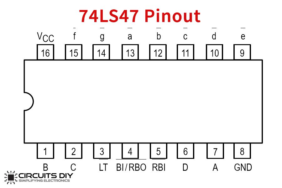
Pinout:
        ┌─────────────┐
   A   -│             │- VCC
   B   -│             │- a (segment a)
   C   -│    7447     │- b
   D   -│             │- c
        │             │- d
  LT   -│             │- e
  RBI  -│             │- f
  BI/RBO-│____________│- g
BCD Input to 7-Segment Output:
| BCD Input (D C B A) | Display |
|---|---|
| 0000 (0) | 0 |
| 0001 (1) | 1 |
| 0010 (2) | 2 |
| 0011 (3) | 3 |
| 0100 (4) | 4 |
| 0101 (5) | 5 |
| 0110 (6) | 6 |
| 0111 (7) | 7 |
| 1000 (8) | 8 |
| 1001 (9) | 9 |
Important: The 7447 is designed for common-anode displays. The display segments light up when the decoder outputs LOW.
7-Segment Display Pinout
Common anode display has all LED anodes connected:
      a
     ───
   ││   ││
  f││   ││b
   ││g  ││
     ───
   ││   ││
  e││   ││c
   ││   ││
     ───
     d

Pin mapping (typical):
1: e, 2: d, 3: Common Anode, 4: c, 5: b, 6: a, 7: f, 8: g
Part 4: Control Logic
Start/Stop Control
Start Button:
- When pressed, enables clock to counters
- Counter begins counting down
Stop Button:
- When pressed, disables clock
- Counter pauses at current value
Implementation using AND gate:
              ┌─────┐
Clock ────────▶│     │
              │ AND ├───▶ To CPU pins of both counters
              │     │
Start/Stop ───▶│     │   (1 = count, 0 = stop)
              └─────┘
Zero Detection and Auto-Stop
When both counters reach 0, the timer should stop automatically.
Logic:
- Ones counter at 0: Q0=0, Q1=0, Q2=0, Q3=0
- Tens counter at 0: Q0=0, Q1=0, Q2=0, Q3=0
Detection using NAND gate:
Ones Q0 ──┐
Ones Q1 ──┼──▶ [NAND] ──┐
Ones Q2 ──┤              │
Ones Q3 ──┘              ├──▶ Stop clock (force to 0)
Tens Q0 ──┐              │
Tens Q1 ──┼──▶ [NAND] ──┤
Tens Q2 ──┤              │
Tens Q3 ──┘              │
When both counters are 0, NAND outputs 0, disabling the AND gate and stopping the clock.
Reset Function
Process:
- Load 60 into both counters
- Enable counting
Circuit:
- Use a pushbutton to pulse PL LOW on both counters
- Data inputs set to 60 (0110 for tens, 0000 for ones)
Part 5: Clock Source
Option 1: 555 Timer IC
The 555 timer can generate a clock signal at a specific frequency.
Astable mode configuration:
        ┌──────────────┐
   VCC -│              │
        │    555      │--[1Hz]--> To counter clock input
   R1 - │    Timer    │
        │             │
   R2 - │             │
        │             │
    C1 -│             │
        │             │
   GND -│_____________│
Frequency formula: f = 1.44 / ((R1 + 2R2) × C1)
For 1 Hz with R1=R2=10kΩ and C=47μF: f = 1.44 / ((10000 + 20000) × 0.000047) f ≈ 1.53 Hz (close enough!)
Option 2: Function Generator
Connect a function generator set to:
- Square wave output
- 1 Hz frequency
- TTL output level
Option 3: Manual Clock (for testing)
Use a pushbutton with debounce circuit for single-step testing.
Part 6: Complete Circuit Diagram
System Integration
+5V ────────────────────────────────────────────────────────────
                                                              │
                                                              │
         ┌─────────────┐         ┌─────────────┐              │
    ────▶│  Clock      │         │  Reset     │              │
         │  Source     │         │  Button    │              │
         └──────┬──────┘         └──────┬──────┘              │
                │                      │                       │
         ┌──────▼──────┐        ┌──────▼──────┐              │
         │  Start/Stop │        │  PL (Load)  │              │
         │   Control   │        │  Both chips │              │
         │   (AND)     │        └─────────────┘              │
         └──────┬──────┘                                       │
                │                                              │
    ────────────┼───────────────────────────────────────────────
                │
      ┌─────────┼─────────┐
      │         │         │
┌─────▼───┐┌────▼────┐┌───▼─────┐
│Ones     ││Tens     ││  Zero   │
│74LS193  ││74LS193  ││ Detector│
│(count 9)││(count 5)││ (NAND)  │
└────┬────┘└────┬────┘└────┬────┘
     │          │          │
     ▼          ▼          ▼
┌────▼───┐┌────▼────┐      │
│ 7447  ││ 7447   │      │
│Decoder││Decoder │      │
└────┬────┘└────┬────┘      │
     │          │          │
     ▼          ▼          ▼
  [7-Seg]   [7-Seg]      (stop)
Part 7: Practice Problem — Build Your Timer
Project Steps
-
Wire the ones counter (74LS193)
- Connect clock input to clock source
- Connect data inputs to 0000 (count down from 0)
- Set MR=0, PL=1
-
Wire the tens counter (74LS193)
- Connect its CPD to TCU of ones counter
- Connect data inputs to 0110 (for 60, load value)
- Set MR=0, PL=1
-
Connect the 7447 decoders and 7-segment displays
- Connect Q outputs of counters to BCD inputs of decoders
- Wire segments to display
-
Add control logic
- Start/Stop AND gate
- Zero detection NAND gates
- Reset pushbutton
-
Test and verify
- Press reset: display should show 60
- Press start: should count down
- At 00: should stop automatically
Show Solution
Step 1: Ones Counter Wiring
- CPU = clock source (through AND gate)
- CPD = HIGH (5V)
- D0-D3 = 0000
- MR = LOW (GND)
- PL = control signal (from reset button)
- Q0-Q3 = to 7447 #1
Step 2: Tens Counter Wiring
- CPU = TCU from ones counter
- CPD = HIGH
- D0-D3 = 0110 (represents 6 for tens digit)
- MR = LOW
- PL = same as ones (from reset button)
- Q0-Q3 = to 7447 #2
Step 3: Decoders
- 7447 #1: A=Q0, B=Q1, C=Q2, D=Q3 from ones counter
- 7447 #2: A=Q0, B=Q1, C=Q2, D=Q3 from tens counter
- Outputs a-g to respective 7-segment displays
Step 4: Control Logic
- AND gate: inputs = clock, start/stop signal
- NAND gates: detect all zeros from both counters
- NAND output = stop signal (disables AND gate)
- Reset: pulse PL low on both counters simultaneously
Step 5: Testing
- Apply power
- Press reset: display should read “60”
- Press start: display counts 59, 58, … 00
- At “00”, counting stops
Summary
- 60-second timer requires two cascaded counters (ones and tens)
- 74LS193 provides up/down counting with parallel load
- 7447 decoder converts BCD to 7-segment display signals
- Cascading uses carry-out from ones to clock-down of tens
- Zero detection stops the clock when both counters reach 0
- Start/Stop control enables or disables the clock signal
- Reset loads the initial value (60) via parallel load
Key Reminders
- Tens counter only needs to count 0-5 (6 states)
- Use common-anode 7-segment displays with 7447 decoder
- Connect TCU to CPD for cascading in the down-count direction for this design
- Always debounce pushbutton inputs to prevent false triggers
- Test each section (counters, displays, controls) before combining
Custom activity — adapted from PLTW Digital Electronics