Activity 2.3.6 — Binary Adders
Learning Objectives
By the end of this lesson, students will be able to:
- Explain the difference between a half adder and a full adder in terms of their inputs and outputs.
- Derive the Boolean expressions for Sum and Cout in both half adder and full adder circuits.
- Build and cascade full adders to create a multi-bit ripple carry adder.
- Verify adder circuits using truth tables and identify the limitations of ripple carry adders.
Vocabulary
Vocabulary (click to expand)
| Term | Definition |
|---|---|
| Half Adder | A combinational circuit that adds two 1-bit numbers, producing a sum and carry output. |
| Full Adder | A combinational circuit that adds two 1-bit numbers plus an incoming carry, producing a sum and carry output. |
| Sum (S) | The result of adding two binary digits; represents the units place of the addition. |
| Carry (C) | The output that represents a “1” to be added to the next higher bit position. |
| Ripple Carry Adder | A multi-bit adder created by cascading full adder circuits, where carries propagate through each stage. |
| 7483 | A 4-bit binary adder IC that performs binary addition on two 4-bit numbers. |
Part 1: Binary Addition Fundamentals
Before building adder circuits, we must understand the rules of binary addition:
Binary Addition Rules
| A | B | Sum | Carry Out |
|---|---|---|---|
| 0 | 0 | 0 | 0 |
| 0 | 1 | 1 | 0 |
| 1 | 0 | 1 | 0 |
| 1 | 1 | 0 | 1 |
These rules follow the same pattern as decimal addition:
- 0 + 0 = 0
- 0 + 1 = 1
- 1 + 0 = 1
- 1 + 1 = 10 (read as “zero with a carry of one”)
Key insight: When adding 1 + 1 in binary, the result is 10 (binary), which means 0 in the current position and 1 carried to the next position.
Part 2: Half Adder
The half adder is the simplest adder circuit. It adds two 1-bit numbers and produces:
- Sum (S) - the result of the addition
- Carry (C) - the carry output to the next bit
Half Adder Inputs and Outputs
- Inputs: A, B (two 1-bit numbers)
- Outputs: Sum (S), Carry (Cout)
Half Adder Truth Table
| A | B | Sum (S) | Carry (C) |
|---|---|---|---|
| 0 | 0 | 0 | 0 |
| 0 | 1 | 1 | 0 |
| 1 | 0 | 1 | 0 |
| 1 | 1 | 0 | 1 |
Half Adder Boolean Expressions
From the truth table:
- Sum (S) = A ⊕ B (XOR gate)
- Carry (C) = A · B (AND gate)
Half Adder Block Diagram
graph LR
    A["A"] --> HA["Half Adder"]
    B["B"] --> HA
    HA --> S["Sum (S)<br/>A XOR B"]
    HA --> C["Carry (C)<br/>A AND B"]

    style HA fill:#fdb,stroke:#333,stroke-width:2px
    style A fill:#bbf,stroke:#333
    style B fill:#bbf,stroke:#333
    style S fill:#bfb,stroke:#333
    style C fill:#bfb,stroke:#333
Half Adder Gate Implementation
 XOR → Sum = A ⊕ B
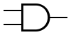 AND → Carry = A · B
Half Adder Circuit
A ----|\
      \_
       )⊕---- Sum (S)
     _/
B ----|

A ----|
      &---- Carry (C)
B ----|
Limitation
The half adder cannot accept a carry-in from a previous stage. It only adds two bits without considering any previous carry. This is why we need the full adder for multi-bit addition.
Key insight: The half adder is a “foundation” block - it’s simple but limited to adding only two 1-bit numbers without carry-in.
Part 3: Full Adder
The full adder solves the half adder’s limitation by accepting three inputs:
- Two data bits (A and B)
- A carry-in (Cin) from the previous bit position
Full Adder Inputs and Outputs
- Inputs: A, B, Cin (three 1-bit values)
- Outputs: Sum (S), Carry Out (Cout)
Full Adder Truth Table
| A | B | Cin | Sum (S) | Cout |
|---|---|---|---|---|
| 0 | 0 | 0 | 0 | 0 |
| 0 | 0 | 1 | 1 | 0 |
| 0 | 1 | 0 | 1 | 0 |
| 0 | 1 | 1 | 0 | 1 |
| 1 | 0 | 0 | 1 | 0 |
| 1 | 0 | 1 | 0 | 1 |
| 1 | 1 | 0 | 0 | 1 |
| 1 | 1 | 1 | 1 | 1 |
Full Adder Boolean Expressions
From the truth table:
- Sum (S) = A ⊕ B ⊕ Cin (cascade of two XOR gates)
- Cout = A·B + Cin·(A ⊕ B) (sum of products)
Full Adder Block Diagram
graph LR
    A["A"] --> FA["Full Adder"]
    B["B"] --> FA
    Cin["Cin"] --> FA
    FA --> S["Sum (S)<br/>A ⊕ B ⊕ Cin"]
    FA --> Cout["Cout<br/>AB + Cin·(A⊕B)"]

    style FA fill:#fdb,stroke:#333,stroke-width:2px
    style A fill:#bbf,stroke:#333
    style B fill:#bbf,stroke:#333
    style Cin fill:#bbf,stroke:#333
    style S fill:#bfb,stroke:#333
    style Cout fill:#bfb,stroke:#333
Full Adder Circuit
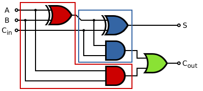
         A ----|----|\
               |    \_
         B ----|---_  )⊕--|\
               |    _/    \_
         Cin ------------|  )⊕--- Sum (S)
                         |/

               A ----|\
                     & |\
               B ---|  )---+---\
                     |/      )---+--- Cout
               A ----|      /
         B ----|          / (XOR from above)
               |         /
         Cin --|________/
Alternatively:
Cout = (A · B) + (Cin · (A ⊕ B))How It Works
The full adder uses XOR to create the sum, which effectively adds all three bits:
- When all three inputs are 0: Sum = 0
- When one input is 1: Sum = 1
- When two inputs are 1: Sum = 0 (but carry = 1)
- When all three inputs are 1: Sum = 1, carry = 1
Key insight: The full adder is essential for multi-bit addition because it handles the carry-in from previous bit positions.
Part 4: Cascading Full Adders (Ripple Carry Adder)
To add multi-bit numbers, we cascade full adders together. Each full adder handles one bit position, and the carry-out from each stage becomes the carry-in for the next stage.
4-Bit Ripple Carry Adder
graph LR
    A0["A0"] --> FA0["Full Adder<br/>Bit 0"]
    B0["B0"] --> FA0
    CIN["Cin=0"] --> FA0
    FA0 --> S0["S0"]
    FA0 -->|"C0"| FA1["Full Adder<br/>Bit 1"]

    A1["A1"] --> FA1
    B1["B1"] --> FA1
    FA1 --> S1["S1"]
    FA1 -->|"C1"| FA2["Full Adder<br/>Bit 2"]

    A2["A2"] --> FA2
    B2["B2"] --> FA2
    FA2 --> S2["S2"]
    FA2 -->|"C2"| FA3["Full Adder<br/>Bit 3"]

    A3["A3"] --> FA3
    B3["B3"] --> FA3
    FA3 --> S3["S3"]
    FA3 --> COUT["Cout"]

    style FA0 fill:#fdb,stroke:#333,stroke-width:2px
    style FA1 fill:#fdb,stroke:#333,stroke-width:2px
    style FA2 fill:#fdb,stroke:#333,stroke-width:2px
    style FA3 fill:#fdb,stroke:#333,stroke-width:2px
    style S0 fill:#bfb,stroke:#333
    style S1 fill:#bfb,stroke:#333
    style S2 fill:#bfb,stroke:#333
    style S3 fill:#bfb,stroke:#333
    style COUT fill:#fbb,stroke:#333,stroke-width:2px
Operation
- Bit 0 (LSB): The first full adder takes Cin = 0 (ground). It produces S0 and C0.
- Bit 1: The second full adder takes C0 as its Cin. It produces S1 and C1.
- Bit 2: The third full adder takes C1 as its Cin. It produces S2 and C2.
- Bit 3: The fourth full adder takes C2 as its Cin. It produces S3 and C3 (final carry out).
Adding 5 + 7 in 4-bit Binary
       5 = 0101
      +7 = 0111
   ------------
       S = 1100 (12)
The carries “ripple” through from right to left, hence the name “ripple carry adder.”
Limitations
The ripple carry adder is simple but slow:
- Each stage must wait for the previous carry to propagate
- In worst case (adding 1111 + 0001), the carry propagates through all stages
- For more speed, carry lookahead adders are used (not covered in this lesson)
Key insight: The ripple carry adder works correctly but has a propagation delay proportional to the number of bits. Each full adder must wait for the previous carry before producing its result.
Part 5: The 7483 4-Bit Binary Adder IC
The 7483 is a classic TTL IC that implements a 4-bit binary adder in a single package:
- Inputs: Two 4-bit numbers (A3A2A1A0 and B3B2B1B0)
- Carry Input: Cin (pin 13)
- Outputs: Four sum bits (S3S2S1S0) and Carry Out (Cout)
- Pins: 16-pin DIP
7483 Pinout
        ┌──────────────┐
 A1 (1) |1     N   16| VCC
 A2 (2) |2            15| A4
 A3 (3) |3     7     14| B4
 A4 (4) |4     4     13| B1
        |     8     5  | B2
 B3 (6) |5     3     12| B4
  S1(7) |6            11| S4
 GND(8) |7     C0    14| S3
        └──────────────┘
(Note: Pin numbers vary slightly by manufacturer - always check the datasheet)
Using the 7483
Simply:
- Apply 4-bit number A to pins A1-A4
- Apply 4-bit number B to pins B1-B4
- Apply carry-in to pin C0 (or ground for 0)
- Read sum output on pins S1-S4
- Read carry-out from pin C4
Example Addition
Adding 1101 (13) + 1011 (11) = 24 (11000):
Inputs:     A = 1101, B = 1011, Cin = 0
Outputs:    S = 1100, Cout = 1
Result: 11000 (binary) = 24 (decimal)
Practice Problem — Half Adder Truth Table
Problem: Complete the half adder truth table and identify the logic gates needed:
| A | B | Sum | Carry |
|---|---|---|---|
| 0 | 0 | ? | ? |
| 0 | 1 | ? | ? |
| 1 | 0 | ? | ? |
| 1 | 1 | ? | ? |
Show Solution
| A | B | Sum | Carry |
|---|---|---|---|
| 0 | 0 | 0 | 0 |
| 0 | 1 | 1 | 0 |
| 1 | 0 | 1 | 0 |
| 1 | 1 | 0 | 1 |
- Sum = A ⊕ B (XOR gate)
- Carry = A · B (AND gate)
Practice Problem — Full Adder Analysis
Problem: For a full adder with inputs A=1, B=1, and Cin=1: a) What is the Sum output? b) What is the Cout output?
Show Solution
From the truth table:
- A=1, B=1, Cin=1 → Sum = 1, Cout = 1
Verification:
- 1 + 1 + 1 = 3 (binary 11)
- Sum bit = 1 (3 mod 2)
- Carry out = 1 (floor(3/2))
Result: 1 + 1 + 1 = 11 (binary) = Sum 1, Cout 1
Practice Problem — Full Adder Gate Implementation
Problem: Draw a circuit diagram for a full adder using XOR, AND, and OR gates. Express both Sum and Cout in terms of A, B, and Cin.
Show Solution
Sum (S): S = A ⊕ B ⊕ Cin
     A ----|\
           \_
            )⊕----|\
     B ----/       \_
                 _ )⊕--- Sum
     Cin ---------/
Cout (C): Cout = A·B + Cin·(A ⊕ B)
     A ----|\
           & |\
     B ---|  )---+---\
          |/      )OR--- Cout
     A ---|       /
     B ---|      /
 Cin ----|     /
         |    /
     (A⊕B)-|---/
Practice Problem — Ripple Carry Addition
Problem: Add the two 4-bit numbers using a ripple carry adder:
- A = 1011 (11)
- B = 0111 (7)
Show each bit position and carry propagation.
Show Solution
        1011   (A = 11)
     +  0111   (B = 7)
     --------
        10010
Step-by-step:
- Bit 0: 1 + 1 = 0, carry 1
- Bit 1: 1 + 1 + carry(1) = 1, carry 1
- Bit 2: 0 + 1 + carry(1) = 0, carry 1
- Bit 3: 1 + 0 + carry(1) = 0, carry 1
Final result: Carry out = 1, Sum = 0010 Total: 10010 (binary) = 18 (decimal) Check: 11 + 7 = 18 ✓
Practice Problem — 7483 IC Application
Problem: Using the 7483 IC, what are the inputs and outputs for adding 9 + 6?
Show Solution
9 = 1001 in binary 6 = 0110 in binary
Inputs to 7483:
- A3A2A1A0 = 1001 (pins A4, A3, A2, A1)
- B3B2B1B0 = 0110 (pins B4, B3, B2, B1)
- Cin = 0 (ground)
Expected Outputs:
- S = 1111 (15)
- Cout = 0
Result: 9 + 6 = 15 ✓
Summary
- The half adder adds two 1-bit numbers: Sum = A ⊕ B, Carry = A · B.
- The full adder adds two 1-bit numbers plus a carry-in: Sum = A ⊕ B ⊕ Cin, Cout = A·B + Cin·(A ⊕ B).
- Full adders cascade to create multi-bit ripple carry adders.
- Each bit position’s carry-out becomes the next position’s carry-in.
- The 7483 is a 4-bit binary adder IC that simplifies multi-bit addition.
- Ripple carry adders are simple but slower than advanced adders due to propagation delay.
Key Reminders
- Binary addition rule: 1 + 1 = 10 (zero with carry)
- Sum output in both half and full adders uses XOR: Sum = A ⊕ B (or A ⊕ B ⊕ Cin for full adder)
- Carry output uses AND: Carry = A · B
- Full adder = 2 half adders + 1 OR gate
- The final carry-out indicates if the sum exceeds the number of bits available.
Custom activity — adapted from PLTW Digital Electronics