Activity 2.3.3 — Multiplexers & Demultiplexers
Learning Objectives
By the end of this lesson, students will be able to:
- Explain the function of a multiplexer (MUX) and demultiplexer (DEMUX) in digital systems.
- Create truth tables for 2:1 and 4:1 multiplexers based on select line combinations.
- Describe how MUX and DEMUX pairs work together to route data from multiple sources to multiple destinations.
- Implement a 4:1 MUX using basic logic gates.
Vocabulary
Vocabulary (click to expand)
| Term | Definition |
|---|---|
| Multiplexer (MUX) | A combinational circuit that selects one of many input signals and forwards it to a single output line based on the state of select lines. |
| Demultiplexer (DEMUX) | A combinational circuit that takes a single input signal and routes it to one of many output lines based on the state of select lines. |
| Select Lines | Input lines that determine which data input is selected (MUX) or which output is enabled (DEMUX). |
| Data Input | The input lines that carry the data to be selected by a multiplexer. |
| Data Output | The output line where the selected data appears in a multiplexer. |
| Enable Input | An input that must be active for the MUX or DEMUX to function. |
Part 1: Introduction to Multiplexers
A multiplexer (MUX) is like a digital switch. It has multiple data input lines, but only one output line. The select lines determine which input is connected to the output at any given time.
The Analogy
Think of a MUX like a rotary switch or a single-pole multi-position switch:
        Switch Position 0 ---- Input 0 ----+
                                           |
        Switch Position 1 ---- Input 1 ----+--> Output
                                           |
        Switch Position 2 ---- Input 2 ----+
                                           |
        Switch Position 3 ---- Input 3 ----+
                    ^
                    |
            Select Lines
2:1 Multiplexer
The simplest MUX has 2 data inputs and 1 select line:
graph LR
    I0["I0"]
    I1["I1"]
    S["S<br/>(Select)"]
    Y["Y<br/>(Output)"]

    I0 --> MUX["2:1 MUX"]
    I1 --> MUX
    S --> MUX
    MUX --> Y

    style MUX fill:#fdb,stroke:#333,stroke-width:2px
    style I0 fill:#bbf,stroke:#333
    style I1 fill:#bbf,stroke:#333
    style S fill:#dfd,stroke:#333
style Y fill:#fbb,stroke:#333| S (Select) | Output (Y) |
|---|---|
| 0 | I0 |
| 1 | I1 |
- When S = 0: Output = Input 0 (I0)
- When S = 1: Output = Input 1 (I1)
4:1 Multiplexer
A 4:1 MUX has 4 data inputs and 2 select lines:
graph LR
    I0["I0"]
    I1["I1"]
    I2["I2"]
    I3["I3"]
    S0["S0"]
    S1["S1"]
    Y["Y<br/>(Output)"]

    I0 --> MUX["4:1 MUX"]
    I1 --> MUX
    I2 --> MUX
    I3 --> MUX
    S0 --> MUX
    S1 --> MUX
    MUX --> Y

    style MUX fill:#fdb,stroke:#333,stroke-width:2px
    style I0 fill:#bbf,stroke:#333
    style I1 fill:#bbf,stroke:#333
    style I2 fill:#bbf,stroke:#333
    style I3 fill:#bbf,stroke:#333
    style S0 fill:#dfd,stroke:#333
    style S1 fill:#dfd,stroke:#333
style Y fill:#fbb,stroke:#333| S1 | S0 | Output (Y) |
|---|---|---|
| 0 | 0 | I0 |
| 0 | 1 | I1 |
| 1 | 0 | I2 |
| 1 | 1 | I3 |
Key insight: With n select lines, a MUX can select from 2^n data inputs. The formula is: Number of data inputs = 2^(number of select lines).
Part 2: 4:1 MUX Truth Table and Implementation
Complete Truth Table
| S1 | S0 | I3 | I2 | I1 | I0 | Y (Output) |
|---|---|---|---|---|---|---|
| 0 | 0 | X | X | X | 0 | 0 |
| 0 | 0 | X | X | X | 1 | 1 |
| 0 | 1 | X | X | 0 | X | 0 |
| 0 | 1 | X | X | 1 | X | 1 |
| 1 | 0 | X | 0 | X | X | 0 |
| 1 | 0 | X | 1 | X | X | 1 |
| 1 | 1 | 0 | X | X | X | 0 |
| 1 | 1 | 1 | X | X | X | 1 |
Note: X means “don’t care” - the value doesn’t matter because that input is not selected.
Boolean Expression
The output Y can be expressed as:
Y = S1'.S0'.I0 + S1'.S0.I1 + S1.S0'.I2 + S1.S0.I3This can be implemented using AND, OR, and NOT gates.
Gate-Level Implementation
2:1 MUX using basic gates:
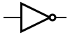 Invert S to get \overline{S}
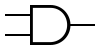 AND gate 1: I0 AND \overline{S}
AND gate 2: I1 AND S
AND gate 1: I0 AND \overline{S}
AND gate 2: I1 AND S
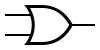 OR combines outputs
graph LR
    I0["I0"]
    I1["I1"]
    S["S"]
    NOT["NOT"]
    S1["\overline{S}"]
    AND1["AND"]
    AND2["AND"]
    OR1["OR"]
    Y["Y"]

    I0 --> AND1
    S --> NOT --> S1
    S1 --> AND1
    I1 --> AND2
    S --> AND2
    AND1 --> OR1
    AND2 --> OR1
    OR1 --> Y

    style NOT fill:#fdb,stroke:#333
    style AND1 fill:#bbf,stroke:#333
    style AND2 fill:#bbf,stroke:#333
    style OR1 fill:#bfb,stroke:#333
    style Y fill:#fbb,stroke:#333,stroke-width:2px
I0 ----|\
& |\
S0' ---| )--+
|/ |
S1' --------+
|
I1 ----|\
& |\
S0 ----| )--+
|/ |
S1' --------+
|
I2 ----|\
& |\
S0' ---| )--+
|/ |
S1 --------+
|
I3 ----|\
& |\
S0 ----| )---- Y
|/ |
S1 ---------+Key insight: The 4:1 MUX implementation uses the select lines and their complements to enable only one AND gate at a time, passing that input to the output OR gate.
Part 3: The 74151 8:1 MUX IC
The 74151 is a common TTL IC that contains an 8:1 multiplexer:
- 8 data inputs: I0 - I7
- 3 select lines: S2, S1, S0 (S2 is MSB)
- 2 outputs: Y (true) and \overline{Y} (complementary)
- Enable (G) input: Active LOW - must be LOW for operation
| S2 | S1 | S0 | Output Y |
|---|---|---|---|
| 0 | 0 | 0 | I0 |
| 0 | 0 | 1 | I1 |
| 0 | 1 | 0 | I2 |
| 0 | 1 | 1 | I3 |
| 1 | 0 | 0 | I4 |
| 1 | 0 | 1 | I5 |
| 1 | 1 | 0 | I6 |
| 1 | 1 | 1 | I7 |
Part 4: Demultiplexers (DEMUX)
A demultiplexer does the opposite of a multiplexer. It takes one input and routes it to one of several outputs, based on the select lines.
The Analogy
Think of a DEMUX like a railroad switch that directs a single train to one of several tracks:
Input -----> [Switch] ---> Track 0
                  |
                  +---> Track 1
                  |
                  +---> Track 2
                  |
                  +---> Track 3
                    ^
                    |
            Select Lines
1:2 Demultiplexer
graph LR
    I["I<br/>(Input)"]
    S["S<br/>(Select)"]
    Y0["Y0"]
    Y1["Y1"]

    I --> DMUX["1:2 DEMUX"]
    S --> DMUX
    DMUX --> Y0
    DMUX --> Y1

    style DMUX fill:#fdb,stroke:#333,stroke-width:2px
    style I fill:#bbf,stroke:#333
    style S fill:#dfd,stroke:#333
    style Y0 fill:#fbb,stroke:#333
    style Y1 fill:#fbb,stroke:#333
1:4 Demultiplexer
graph LR
    I["I<br/>(Input)"]
    S0["S0"]
    S1["S1"]
    Y0["Y0"]
    Y1["Y1"]
    Y2["Y2"]
    Y3["Y3"]

    I --> DMUX["1:4 DEMUX"]
    S0 --> DMUX
    S1 --> DMUX
    DMUX --> Y0
    DMUX --> Y1
    DMUX --> Y2
    DMUX --> Y3

    style DMUX fill:#fdb,stroke:#333,stroke-width:2px
    style I fill:#bbf,stroke:#333
    style S0 fill:#dfd,stroke:#333
    style S1 fill:#dfd,stroke:#333
    style Y0 fill:#fbb,stroke:#333
    style Y1 fill:#fbb,stroke:#333
    style Y2 fill:#fbb,stroke:#333
    style Y3 fill:#fbb,stroke:#333
1:4 Demultiplexer Truth Table
| S1 | S0 | Input (I) | Y3 | Y2 | Y1 | Y0 |
|---|---|---|---|---|---|---|
| 0 | 0 | 0 | 0 | 0 | 0 | 0 |
| 0 | 0 | 1 | 0 | 0 | 0 | 1 |
| 0 | 1 | 0 | 0 | 0 | 0 | 0 |
| 0 | 1 | 1 | 0 | 0 | 1 | 0 |
| 1 | 0 | 0 | 0 | 0 | 0 | 0 |
| 1 | 0 | 1 | 0 | 1 | 0 | 0 |
| 1 | 1 | 0 | 0 | 0 | 0 | 0 |
| 1 | 1 | 1 | 1 | 0 | 0 | 0 |
When select lines = 00, input goes to Y0. When select lines = 01, input goes to Y1, etc.
Key insight: A 1:4 DEMUX has 1 input, 2 select lines, and 4 outputs. In general, a DEMUX with n select lines can route to 2^n outputs.
Part 5: MUX/DEMUX Communication System
Multiplexers and demultiplexers are often used together in communication systems to share a single transmission line among multiple data sources.
How It Works
Source 0 ----MUX----> Transmission Line ----DEMUX----> Destination 0
Source 1 ----MUX----> (shared path)          ----DEMUX----> Destination 1
Source 2 ----MUX---->                        ----DEMUX----> Destination 2
Source 3 ----MUX---->                        ----DEMUX----> Destination 3
graph LR
S0["Source 0"] --> MUX["4:1 MUX"]
S1["Source 1"] --> MUX
S2["Source 2"] --> MUX
S3["Source 3"] --> MUX
SEL1["Select<br/>Lines"] --> MUX
MUX -->|"Shared<br/>Transmission<br/>Line"| DMUX["1:4 DEMUX"]
SEL2["Select<br/>Lines"] --> DMUX
DMUX --> D0["Dest 0"]
DMUX --> D1["Dest 1"]
DMUX --> D2["Dest 2"]
DMUX --> D3["Dest 3"]
style MUX fill:#fdb,stroke:#333,stroke-width:2px
style DMUX fill:#fdb,stroke:#333,stroke-width:2px
style S0 fill:#bbf,stroke:#333
style S1 fill:#bbf,stroke:#333
style S2 fill:#bbf,stroke:#333
style S3 fill:#bbf,stroke:#333
style D0 fill:#bfb,stroke:#333
style D1 fill:#bfb,stroke:#333
style D2 fill:#bfb,stroke:#333
style D3 fill:#bfb,stroke:#333The MUX at the sender combines multiple signals into one. The DEMUX at the receiver separates them back to their original destinations.
Both MUX and DEMUX must use the same select lines to ensure the correct data is routed.
Applications
- Data routing: Select between multiple input sources to send to one output
- Parallel-to-serial conversion: Convert parallel data to serial by using select lines to clock through each bit
- Function generation: Use MUX inputs tied to HIGH/LOW to create custom truth table outputs
- Communication systems: Share communication channels among multiple users
Key insight: MUX and DEMUX are inverse operations. A MUX combines signals while a DEMUX separates them. They work as a pair when sending data over a shared transmission path.
Practice Problem — MUX Truth Tables
Problem 1: Complete the truth table for a 2:1 MUX with inputs I0, I1 and select line S.
| S | I1 | I0 | Output (Y) |
|---|---|---|---|
| 0 | 0 | 0 | ? |
| 0 | 0 | 1 | ? |
| 0 | 1 | 0 | ? |
| 0 | 1 | 1 | ? |
| 1 | 0 | 0 | ? |
| 1 | 0 | 1 | ? |
| 1 | 1 | 0 | ? |
| 1 | 1 | 1 | ? |
Show Solution
| S | I1 | I0 | Output (Y) |
|---|---|---|---|
| 0 | 0 | 0 | 0 |
| 0 | 0 | 1 | 1 |
| 0 | 1 | 0 | 0 |
| 0 | 1 | 1 | 1 |
| 1 | 0 | 0 | 0 |
| 1 | 0 | 1 | 0 |
| 1 | 1 | 0 | 1 |
| 1 | 1 | 1 | 1 |
When S=0, Y follows I0. When S=1, Y follows I1.
Practice Problem — Draw MUX Circuits
Problem: Draw a circuit diagram for a 4:1 MUX using AND, OR, and NOT gates. Label all inputs (I0-I3), select lines (S0, S1), and the output (Y).
Show Solution
           I0 ---|\
                 & |\
           S0' -|  )---+   \
           S1' -|        )---+--> Y
           I1 -|  /    /   /
           S0 --| /    /---+
           S1' -|/
               |
           I2 -|\
                 & |\
           S0' -|  )---+
           S1 ---|        )---+
           I3 -|  /    /   /
           S0 --| /    /---+
           S1 ---|/
Key points:
- Each AND gate receives one data input
- Each AND gate also receives the appropriate combination of S0, S0’, S1, S1’
- Only ONE AND gate is enabled at a time based on select line values
- All AND gates feed into a final OR gate
Practice Problem — DEMUX Analysis
Problem: For a 1:2 DEMUX with select line S, input I, and outputs Y0 and Y1, determine: a) What is the output when S = 0? b) What is the output when S = 1?
Show Solution
a) When S = 0: Input I is routed to Y0. Y0 = I, Y1 = 0 b) When S = 1: Input I is routed to Y1. Y0 = 0, Y1 = I
Summary
- A multiplexer (MUX) selects one of many inputs to appear on a single output based on select lines.
- A demultiplexer (DEMUX) takes one input and routes it to one of many outputs based on select lines.
- With n select lines, a MUX can select from 2^n inputs, and a DEMUX can route to 2^n outputs.
- The 74151 is a common 8:1 MUX IC with 3 select lines.
- MUX and DEMUX pairs are used together in communication systems to share transmission paths.
- MUX can be implemented using AOI (AND-OR-INVERT) gates.
Key Reminders
- Remember the MUX rule: Number of inputs = 2^(number of select lines).
- MUX selects data; DEMUX distributes data.
- Select lines must match between paired MUX and DEMUX for proper communication.
- The 74151 has complementary outputs (Y and \overline{Y}).
- MUX can be used to implement any combinational logic function by tying inputs to HIGH or LOW according to the truth table.
Custom activity — adapted from PLTW Digital Electronics