Activity 2.3.2 — Seven-Segment Display
Learning Objectives
By the end of this lesson, you will be able to:
- Identify the seven segments (a-g) and explain the difference between common cathode and common anode configurations.
- Map binary-coded decimal (BCD) values to the required segments for digits 0-9.
- Wire a BCD-to-7-segment decoder circuit with proper current-limiting resistors.
Materials
- 1 Common Cathode Seven-Segment Display
- 1 74LS47 or 74LS48 BCD-to-7-Segment Decoder
- 7 330 Ω Resistors
- Digital Trainer or 5V Power Supply
- Jumper Wires
- Optional: Multisim / Wokwi for simulation
Part 1: Display Anatomy
A seven-segment display uses eight LEDs (a-g + decimal point) to represent digits and letters.
Common Cathode vs Common Anode
| Configuration | Description | Logic to Light Segment | |--------------|-------------|-------------------------| | Common Cathode | All cathodes to GND | HIGH (1) | | Common Anode | All anodes to VCC | LOW (0) |
Part 2: Procedure — Digit Mapping
Complete the truth table below by determining which segments must be illuminated to display the digits 0-9. Use “1” for ON and “0” for OFF.
Digit Mapping Task
- Study the segment layout (a-g) shown in the diagram above.
- Click each cell in the truth table below to toggle it ON (1) or OFF (0). The seven-segment preview updates in real-time so you can verify your answer visually.
Seven-Segment Truth Table
Click cells to toggle: empty → 1 → 0 → emptySelected Digit
0
Segment Layout:
a top b top-right c bottom-right d bottom e bottom-left f top-left g middle| Digit | a | b | c | d | e | f | g |
|---|---|---|---|---|---|---|---|
| 0 | |||||||
| 1 | |||||||
| 2 | |||||||
| 3 | |||||||
| 4 | |||||||
| 5 | |||||||
| 6 | |||||||
| 7 | |||||||
| 8 | |||||||
| 9 |
Fill in all cells to submit
Part 3: Procedure — Circuit Construction
The Decoder
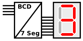
The 7447/7448 IC takes a 4-bit BCD input and decodes it into the 7-segment outputs.
Wiring Steps
- Place the 7-segment display on your breadboard straddling the center gap.
- Connect the Common pin to GND (for common cathode).
- Connect each segment pin (a-g) through a 330 Ω resistor to the corresponding output on the decoder IC.
- Set your inputs (A, B, C, D) using switches on the digital trainer.
Conclusion Questions
Answer the following based on your laboratory experience.