Activity 1.1.5 — Breadboarding & Circuit Prototyping
Learning Objectives
By the end of this lesson, you will be able to:
- Explain the purpose and structure of a solderless breadboard
- Identify power rails, terminal strips, and the center gap
- Apply best practices for breadboard circuit construction
- Build a simple LED circuit on a breadboard
- Troubleshoot common breadboard wiring problems
Materials
- 1 Solderless breadboard (400 or 830 point)
- 1 330 $\Omega$ Resistor
- 1 LED (any color)
- 5V Power Supply (Digital Trainer or Power Module)
- Jumper Wires (Solid core 22 AWG)
Part 1: Breadboard Anatomy
Breadboards provide a reusable platform for building and testing electronic circuits.
How Breadboards Work
Inside a breadboard are metal strips with clips that hold component leads. Holes in the same row are electrically connected.
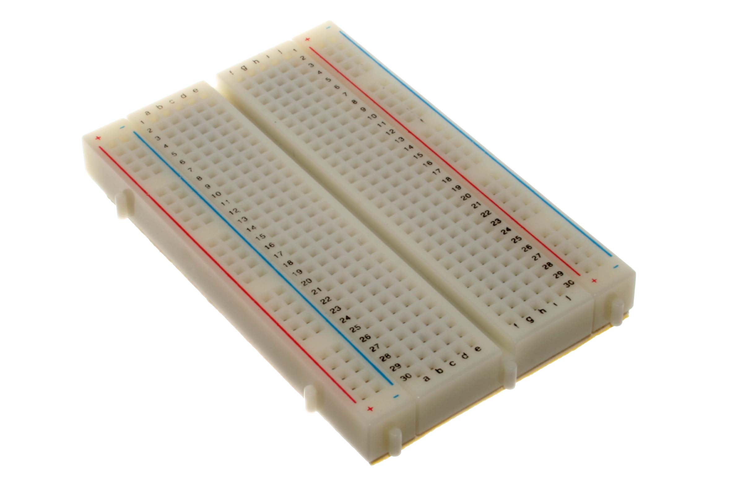
| Zone | Purpose | Connection Type | |------|---------|----------------| | Power rails | Distribute power (+ and -) | Vertical columns, full length | | Terminal strips | Connect components | Horizontal rows, 5 holes each | | Center gap | For ICs to straddle | No connection across gap |
Part 2: Best Practices
- ICs Straddle the Gap: Place ICs across the center gap to isolate each pin.
- Minimize Jumper Wires: Use component leads to bridge gaps where possible.
- Short Leads: Trim or bend leads to keep components flush to the board.
- Color Code: Use Red for power and Black for ground.
Part 3: Procedure — Simple LED Circuit
Follow the schematic below to build a basic LED circuit.
The Schematic
+5V ----+---- R (330 ohm) ----+---- LED (anode) ---- LED (cathode) ---- GNDBuild Steps
- Place the resistor with one lead in a terminal strip and the other in the positive (+) power rail.
- Place the LED with the anode (long lead) in the same row as the resistor output.
- Connect the LED cathode (short lead) to the ground (-) power rail.
- Connect the power module (+5V and GND) to the breadboard rails.
Part 4: Procedure — Parallel LED Challenge
Objective: Modify your circuit to include a second LED in parallel with the first. Both LEDs should light with equal brightness.
Challenge Constraints
- Use a single resistor to limit current for both LEDs.
- Both LEDs must be clearly visible in your photo.
Conclusion Questions
Answer the following questions based on your laboratory experience.